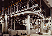
Incinerator for Waste Liquids Containing Solid Particles
Waste liquids containing solid catalyst particles at chemical plants can be thermally cracked by effective contact with the combustion flame of the auxiliary fuel burner of the V-II type vertical incinerator.
Combustion gas is quenched in the direct contact type quenching chamber at the bottom and solid materials are recovered by a venturi scrubber.
The incineration and the thermal cracking process are performed effectively using the space and walls of the incinerator.
Recovery of solid materials is possible even if the ratio of the solids in the waste liquid is as high as 30% - 40%.
")
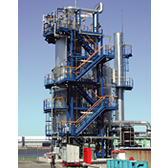
Incinerator for Halide Wastes
Generally, it is difficult to thermally crack liquid waste and gas containing halides such as fluorine, chlorine, bromine, and indine.
Even if cracking and incineration are done effectively, the processed waste and/or gas has to be carefully handled in equipment constructed of special materials.
NFK has successfully overcome the technical difficulties and has developed a reliable incineration and thermal cracking system.
The refractory lining materials of the incinerator are designed in accordance with the specific nature of the halides to be fed into the system.
The combusted waste gas from combustion chamber flows to the scrubbing tower after it is quenched in the quenching chamber at the bottom and scrubbed by the alkaline liquid in the scrubbing tower filled with special packing materials.
The concentration of halides in the exhaust gas can fully meet the strict environmental regulations.
")
Incinerator for Waste Liquids and Waste Gas
The system consists of a combustion chamber, a quenching chamber, a bag filter and an exhaust stack.
In the combustion chamber, waste liquid and/or the gas is incinerated using high temperature auxiliary fuel firing gas. It is then quenched in the quenching chamber.
The quenched gas is fed, and filtered by the bag filter and diffused to the atmosphere from the stack.
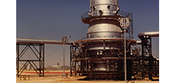
Acid Gas Incinerator
Acid gas which contains H2S, is produced by the desulfurization processes in oil and LNG refining plants.
This incinerator oxidizes such toxic gases and hydrocarbons converting into SO2, CO2 and H2O.
Either natural draft or forced draft is applicable for this system.
No auxiliary fuel firing is required when the LHV of acid gas is over 3,500kJ/Nm3.
Tail Gas Incinerator for Sulfur Recovery Unit
This incinerator is designed to oxidize sulfur compound (H2S, COS, CS2. Sn) in tail from SRU and/or off gas from TGTU using auxiliary fuel firing.
Treating gas is fed through branched lines of the header part to the incinerator.
This makes possible the complete mixing of treating gas and high temperature gas produced by combustion of auxiliary fuels.
")
Equipment for Waste Plastics Liquefaction Plant
The waste plastic liquefaction process was jointly developed by NFK and Chiyoda Corporation.
NFK constructed and supplied a thermal cracking vessel, a residue extracting unit, a reheating furnace and a waste gas (contains HC l) incinerator for the plant.
")
Cyclone Melting Furnace for Sewage Sludge
NFK supplied a cyclone melting furnace for sewage sludge for a sewage disposal plant constructed by JGC Corporation.